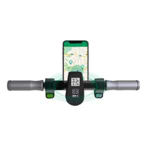
Most eBikes have one piece of LCD or LED display mounted on the center of the handlebar while few others have two, the second of which is always placed on the side of the bar. The display provides basic riding information such as speed, range, and battery remaining for the riders, in addition to allowing riders to control and switch between each padel assistant level.
The display comprises a circuit board containing chips and many other components for various purposes.
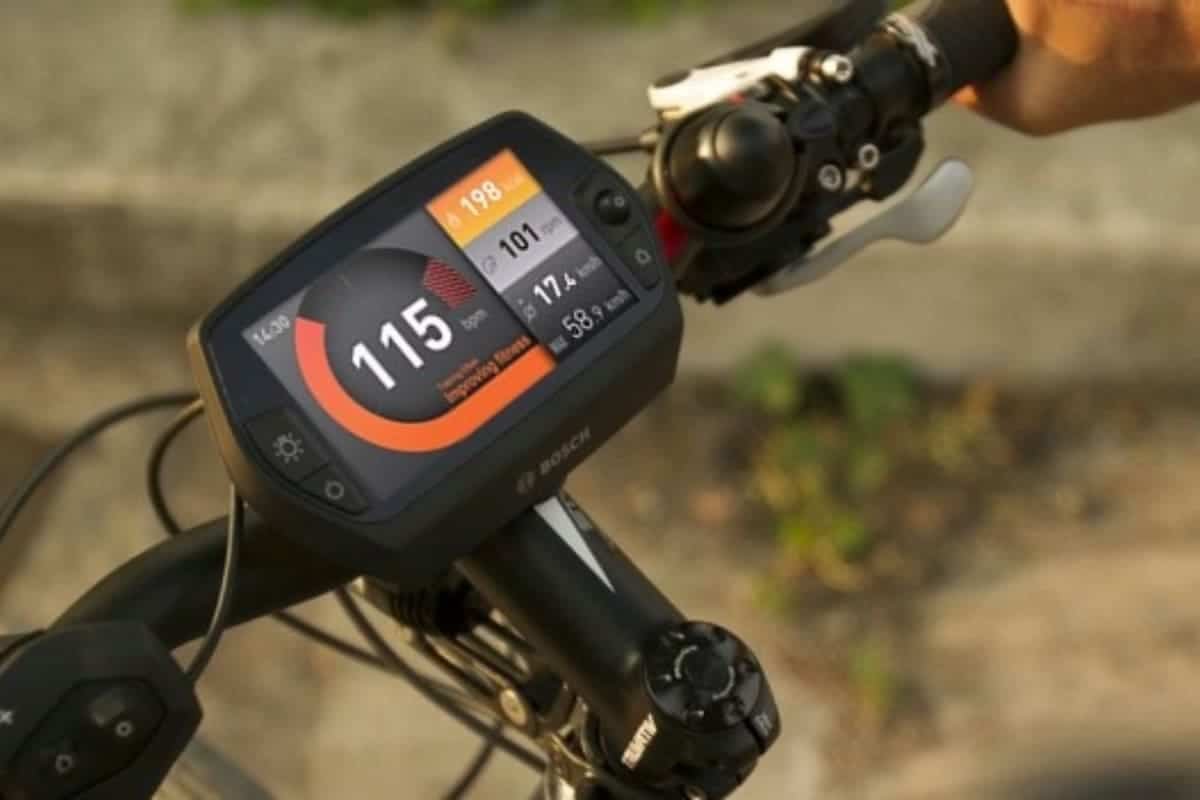
The chosen design and components determine the advantages of a display, such as how accurate the speed and range it shows and how many features it has. (Some displays have percentage-based battery readout to tell precisely how much battery has left).
Some features you could add to the display of your building e-bike to make it stand out from the pack.
- Tells riders how much carbon and trees you have saved
- Accurate percentage-based battery readout, which helps figure out how much further you could go
- A handlebar-mounted headlight can be controlled via LCD
- Class2 to class 3- For some eBikes, they are class 2; that is how the manufacturer ships and how the manufacturer advertises to meet the rules or the laws and regulations of the states. However, users can change it to class 3 with ease.
- Vibration feedback of the buttons on display, so users would know the buttons are being pressed so they can keep their eyes on the road without having to come down and focus on little words on display every time they ride around.
However, the production process is another critical factor affecting the final quality of the display. Any errors or poor operations during the making process would cause an enormous lousy consequence.
Here on this page, we’d like to share the process of making the display for an eBike and how we ensure each component is in its place correctly every time we put them on the board, playing their proper roles.
Table of Contents
- 1, Surface Mount Assembly
- 2, Solder Paste Inspection
- 3, Pick and Place
- 4, Pre-Inspection Before Heated Up
- 5, Melt The Solder
- 6. Automatic Optical Inspection
- 7, Circuit Board Function Inspection
- 8, Put On The Glass
- 9 Final Testing
- 10, Laser Engraved
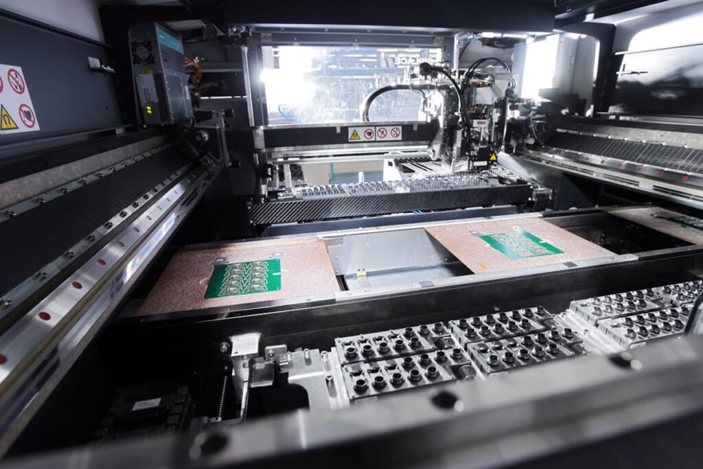
1, Surface Mount Assembly
This is a circuit board with all these little copper pads waiting for components to be put on. In order to put them in the right place appropriately aligned with the right amount of solder paste, we need a stencil and a surface mount assembly machine.
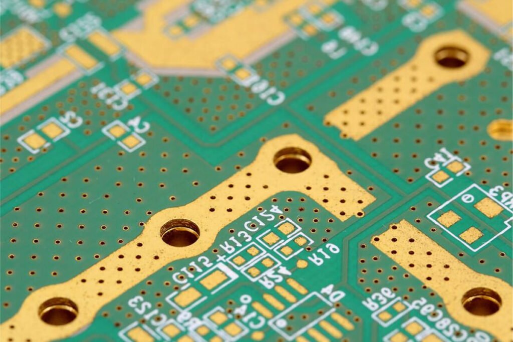
This is a stencil, a piece of stainless steel with lots of laster cut holes where the solder paste will go through.

The first step of pasting components onto the board is applying the solder paste, which then would be heated up in the oven and transferred as metal, being an excellent electrical joint.
The surface mount machine is pretty as a squeegee sweeping the solder paste on the stencil to finish the first step.
2, Solder Paste Inspection
The solder paste in the right place with the correct amount is the foundation before going through all the other steps.
This high-tech machine is used to inspect the previous step to ensure the solder paste fits the IPC standard.
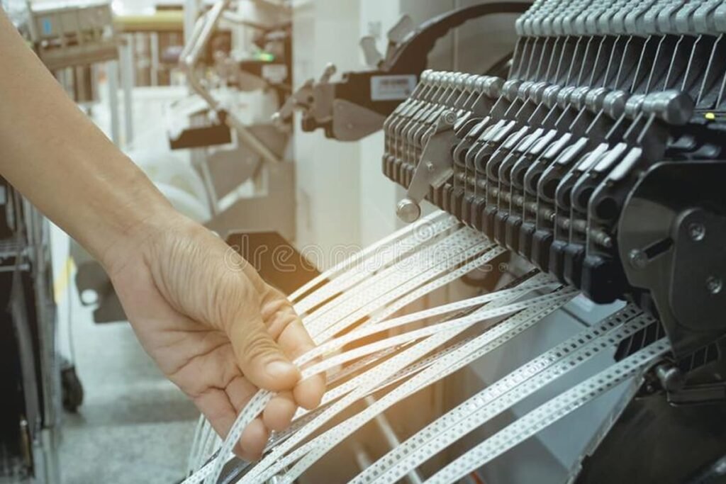
3, Pick and Place
All the components were put in the reels like this, which were sent to the factory ready to be pasted.
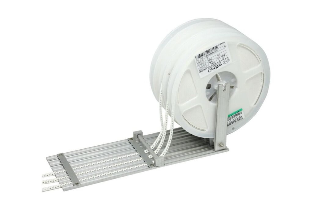
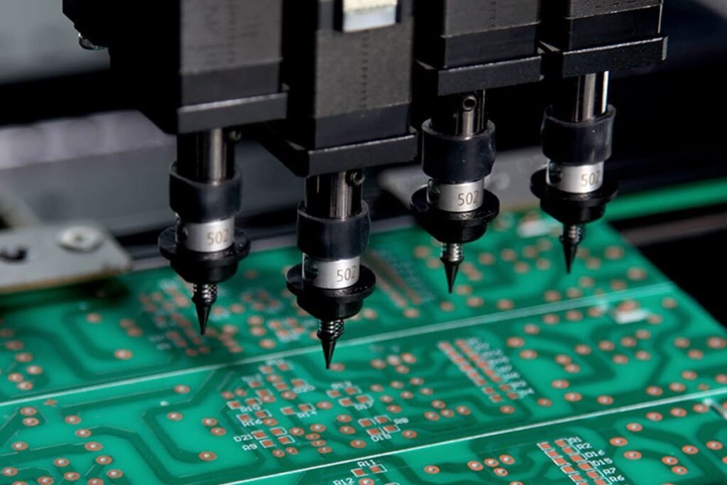
This is the pick and place machine that takes all these little parts out of the reels and puts them into the solder paste, which has been applied from the last step.
To make this process accurate, we have cameras on the pick and place machine and registration marks on the circuit boards, which are usually round circles with a dot in its center that are put on the board by the designer.
When the circuit boards come into the machine, the camera will do its work finding all these marks, thus knowing where components should be put.
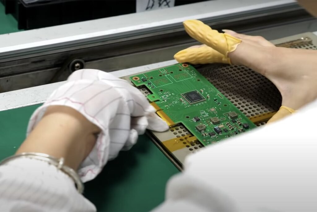
4, Pre-Inspection Before Heated Up
Before the circuit board is ready to get heated up, we need to do some pre-inspection to test the value of each component installed on the board, especially for capacitors and resistors which look very similar to each other, to make sure they are in the right values.
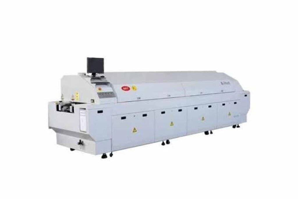
5, Melt The Solder
After the pre-test, the circuit board will go into this reflow oven to melt the solder. The temperature curve is raised in the oven to meet its max value where the solder melts, then gradually cooling down before coming out from the end.
6. Automatic Optical Inspection
AOI refers to the automatic optical inspection, which uses a different color of rainbow light to see whether all these solder joints that came out of the reflow oven look correct.
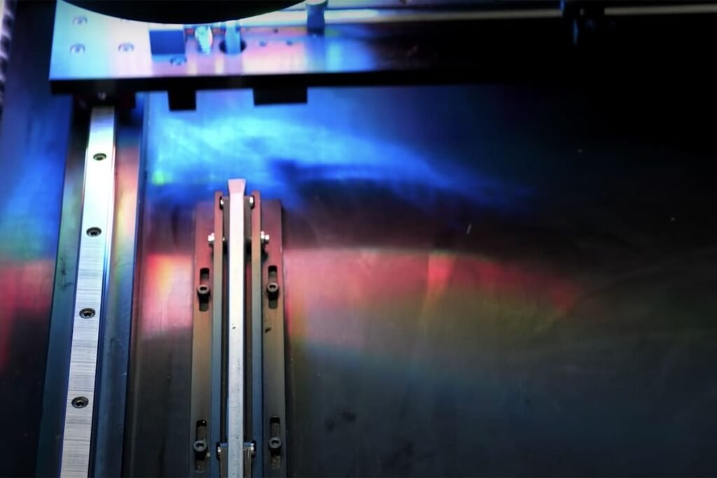
Firstly, we take a circuit board that has been tested and visually inspected that we know the perfect golden master.
And secondly, we get a whole bunch of pictures from this golden master at every different angle using the rainbow light inside the machine. This bunch of pictures is the standard version for comparison to every current board coming out of the oven.
The AOI machine will then automatically catch anything unusual, and the inspectors will check it visually and then mark it with a problem tag. Once it is confirmed, then someone will take it to another place where to fix it.

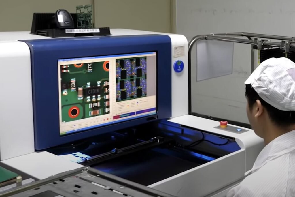
7, Circuit Board Function Inspection
The six steps above ensure every little part is appropriately put on the circuit board, and the last step is to check whether the board can achieve all the expected functions.
This step is some electrical testing.
We use the testing jig with spring-loaded pins that connect the testing points custom designed on the board. The jig will power up the board and see if it works correctly, and it includes the software and programmed project testing.

8, Put On The Glass
We have the solid circuit board, and now we need to mount the clamshell of the display together; we use the supersonic mounting machine to do the job.
And we put the glass onto the circuit board in a sterilized room with a steamer and ventilation inside to ensure everything works properly.
9 Final Testing
Skilled workers go through every display function right after the glass is put on.
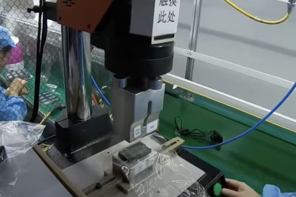
10, Laser Engraved
The last step is to put serial numbers on display for service or tracking purposes, as well as customers’ brand names if required.